Rheometer geometries: relative measuring geometries
Relative measuring geometries are used with rheometers to characterize a wide range of samples. A relative measuring geometry delivers values which are relative values (as opposed to absolute values). Relative values are specific to the geometry used. With relative geometries; results are only comparable when using the same geometry. Relative geometries include spindles, vane rotors, stirrers, and geometries with sandblasted, profiled, or serrated surfaces. This article gives an overview of the different relative geometries available, where they are used, and what to consider when using them.
Relative vs. absolute measuring systems
The calculation of rheological parameters in the form of absolute units which are independent of the individual measuring geometry used, from raw data which is measured by the rheometer, is only possible if standardized absolute measuring geometries (measuring systems) are taken. Absolute measuring geometries include:
- concentric cylinders CC
- cone-and-plate CP
- parallel-plates PP
- double gap DG
- and measuring systems according to ISO 3219-2 and DIN 53019.
For example: A liquid is tested using two ISO standard cylinder geometries of different sizes. Due to the larger shear area of the the larger one, the rheometer measures a higher torque value although the same rotational speed was preset. Nevertheless, finally the same viscosity value is calculated from the two different raw data, since there are different conversion factors for the two measuring geometries to calculate the same shear stress value from the different torque values. The values determined by the larger geometry can be compared with the values determined by the smaller geometry.
When using relative measuring geometries, however, the shear conditions in most cases are not as clearly defined as required for an accurate rheological analysis.
Using relative measuring geometries in rotational tests
When performing rotational tests using relative measuring geometries, fluids often flow inhomogeneously, showing secondary flow effects like turbulent flow with vortices instead of the desired laminar flow, or time-dependent effects occur, such as transient flow effects. In these cases, it is impossible to calculate shear rate values from the raw data, since with relative geometries neither the geometry nor the dimension of the shear gap meet the required standard conditions (according to ISO 3219-2 or DIN 53019). Thus, viscosity values cannot be calculated, measuring point by measuring point, according to the law of Newton, since defined shear rate values are not available at all. In other words:
When using relative measuring geometries with rotational tests, the shear conditions required to determine the shear viscosity values of liquids are not met, e.g. in the form of laminar flow.
Using relative measuring geometries in oscillatory tests
Also when performing oscillatory tests, creep tests, and relaxation tests using relative measuring geometries to determine the viscoelastic behavior of gels, pastes, and solids, the required shear conditions are not exactly defined. If the sample shows viscoelastic behavior, the shear process will be inhomogeneous. In this case, the following values cannot be calculated exactly:
- viscosity
- shear moduli
- values based on the viscosity law (acc. to Newton)
- values based on the elasticity law (acc. to Hooke)
- values based on the relations of Maxwell, Kelvin/Voigt, and Burgers
- values defined according to the ISO and DIN standards
Defined deformation values are required in order to calculate these values and with relative geometries neither the geometry nor the dimensions of the shear gap meet the required conditions for an accurate calculation. In other words:
When using relative measuring systems, the shear conditions required to determine absolute values of parameters to describe the rheological properties of viscoelastic samples are not met, e.g. in the form of homogeneous deformation behavior in the entire shear gap.
According to ISO 3219-2, test results obtained with relative measuring geometries should be specified in terms of relative values, e.g. as relative viscosity or relative shear modulus, and not in terms of absolute units, i.e. not as viscosity values in Pa.s and not as shear moduli in Pa; and the same holds for the storage modulus G’ and the loss modulus G’’ obtained from oscillatory tests with relative geometries. In this case, the results should be presented in terms of instrument units or measuring geometry units, for example, in terms of relative torque values, in percent of the total torque.
Types of relative measuring geometries
There are numerous relative measuring systems available. Some have been designed for one specific application, others are more generally applicable. The following sections describe the different geometries and their applications.
Measuring geometries with sandblasted, profiled, or serrated surfaces
When effects like wall slip occur on the surfaces of a measuring geometry, it is useful to take a system with a rough surface instead of the usually smooth and polished surface in order to guarantee adhesion between the sample and the wall of the measuring geometry. Typical samples which are well-suited for measurement with rough-surface geometries are:
- Mayonnaise
- Hand cream
- Peanut butter
- Lube greases and waxes
Usually parallel-plate geometries with sandblasted surfaces are used. As a comparison: In ISO 6721-10 for smooth-plate surfaces a maximum roughness of 0.25 µm is recommended. With modified surfaces, either only the surface of the rotating plate is roughened or both surfaces are roughened (both the upper and the stationary bottom plate).
For all samples containing oil and fat it is recommended to use sandblasted surfaces for at least that part of the measuring geometry which is set in motion. This therefore applies for many samples from the pharmaceutical, cosmetics, medical, and food industries; and it is also valid for many petrochemicals such as lube greases, waxes, and vaselines.
For very slippery samples and for materials exhibiting interfacial slippage or gliding effects along external surfaces, and for sliding rigid solids, it is sometimes necessary to use a measuring geometry with a profiled or serrated surface, for example when testing gels, waxes, elastomers, rubbers, or hard cheese. Often only the rotor is profiled. However, for measuring materials with a strong tendency to slip, the test result will be improved significantly when also a profiled stationary part of the measuring geometry is used.
Sometimes even cylinder systems are used with bobs with sandblasted surfaces, and rarely also the cups have sandblasted surfaces, or the bobs are milled lengthways (see Figure 1, no. 3) or in the form of spiral lines (Figure 1, no. 4).
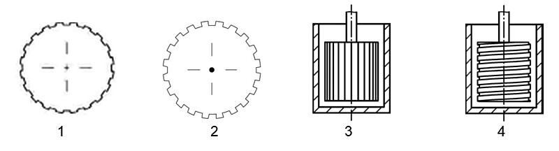
Figure 1: Cross-sections of profiled cylinder measuring bobs (1 and 2) [1, 2], a cylinder with vertical profiling on the measuring bob (and possibly also on the measuring cup) to prevent wall slip (3), and a cylinder with a helical spiral groove on the measuring bob to prevent sedimentation (4) [3]
Rheometer users working in scientific fields should be aware of the following: All surfaces which are not smooth disturb the laminar flow conditions and therefore turbulent flow conditions may be generated causing vortices in the boundary layer between the liquid sample and the surface of the measuring geometry. However, since laminar flow is a pre-condition for the validity of the viscosity law, results which are attained with rough surfaces should be considered relative values in principle. This holds even though the obtained measuring data is sometimes quite similar to that obtained when using smooth surfaces. The difference between the results is sometimes hardly noticeable, especially under low-shear conditions, i.e. below the shear rate of 1 s-1. However, the effects may be significant when determining the values of the yield stress and the flow stress, when measuring within the yield zone, and when performing LAOS tests (yield zone, e.g. for amplitude sweeps between yield stress and flow stress).
Spindles in the form of disks and pins (acc. to ISO 2555 and ISO 3219-2) <sup>[3, 4]</sup>
These measuring geometries mostly consist of a single part which is usually called a spindle (sometimes it is called a rotor). There are spindles with a variety of different designs; they are typically used in QC laboratories since they are frequently used for simple tests.
Typical spindles have:
- the shape of disks exhibiting a thickness h and a diameter d comparable to coins, usually showing d = approx. 13 mm to 50 mm and h = approx. 2 mm or 7 mm;
- or the shape of pins showing d = approx. 3 mm or 6 mm and a cylindrical length L = approx. 15 mm to 50 mm;
- or the shape of cylinders showing d = approx. 10 mm or 20 mm and L = approx. 55 mm or 65 mm.
The following three series of spindle sets are used most frequently (see Figure 2):
1) The spindles LV-1 to LV-5: LV-1 as a cylinder, LV-2 and LV-3 as disks showing different diameters and thickness, LV-4 and LV-5 as pins showing different lengths
2) The spindles RV-1 to RV-7 (as HA and HB): RV-1 as a hollow cylinder, RV-2 to RV-6 as thin disks showing different diameters, and RV-7 as a pin
3) The cross-bar or so-called T-bar for the helipath drive system. Here, a pin is attached right-angled to the rotation axis. There are six bars available showing different lengths. This geometry is used to measure non-flowing, paste-like samples.
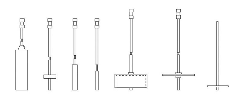
Figure 2: Various spindle geometries (from left to right): type LV in the form of cylinders, thick disks and pins, type RV as a hollow cylinder and thin disks, and on the right: a T-bar [3]
With spindle geometries the test results are often specified in the form of a relative torque value Mrel with the unit [%] related to the maximum torque of the viscometer used. Some users just mention the values of the dial reading (DR) then. For most of the spindles, the shear stress might be calculated from the measured torque since the geometry and size of the shear area is known.
The shear rate, however, is not defined, and there is no narrow shear gap existing as for the standard measuring geometries according to ISO 3219-2 or DIN 53019. For analysis, the shear gap is therefore termed “infinitely wide”, i.e. the cup radius R is assumed to be: R = infinity. The geometrical conditions are, for example, called a “dip-in spindle being in an infinite sea of fluid” [5], e.g. when measuring in a typical 600 mL glass beaker showing an inner diameter of 85 mm. For this reason, homogeneous shear conditions throughout the entire sample cannot be guaranteed. Also, when using a disk-like spindle, the cylindrical length of the shear gap corresponds in fact just to the very small thickness of the disk which is often 2 mm only. In this case, a useful shear gap dimension cannot be specified. Due to this, these kinds of measuring geometries produce more incalculable edge effects and, therefore, more turbulent flow conditions showing vortices than laminar flow conditions.
When using spindles (acc. to ISO 2555), viscosity values are not absolute values but relative values.
Problems when calculating viscosity from values determined by spindles
According to the viscosity law (acc. to Newton), it is not possible to calculate viscosity values without defined shear rate values. Therefore, viscosity specifications which are based on tests performed with these kinds of spindles are relative viscosity values and should be termed as such, or termed as values which are dependent on the instrument or measuring system used. Comparing values which are determined with spindles and specified in mPa.s or Pa.s with absolute viscosity values which are measured using absolute measuring geometries will, in almost all cases, result in deviations due to the above reasons.
After many comparative tests, it might be possible to find a certain approximative correlation between test results obtained with an individual spindle and an individual ISO standard measuring system. However, in this case the correlation only applies for these two measuring geometries and only for that individual liquid sample used, and even then only if this fluid shows ideally viscous flow behavior. Comparability cannot be expected for non-Newtonian materials, and that counts particularly for different rotational speeds. If conversion formulas are given in literature, they are based on empirical tests which are performed in a limited range of rotational speeds which was individually chosen for a certain group of samples from a certain application field. These kinds of formulas should not be overrated since in most cases they are only useful for a rough estimate of the rheological behavior of a sample.
Krebs spindles
Krebs spindles are used for simple routine tests in the coatings industry, for example according to ASTM D562 for paints [6].
The Krebs spindle consists of a stirrer with two blades, i.e. it has a shaft on which are attached two paddle-shaped agitator blades, each one approximately 24 mm (length) and 8 mm (width; see Figure 3, right). Therefore, some users call it a “paddle system”.
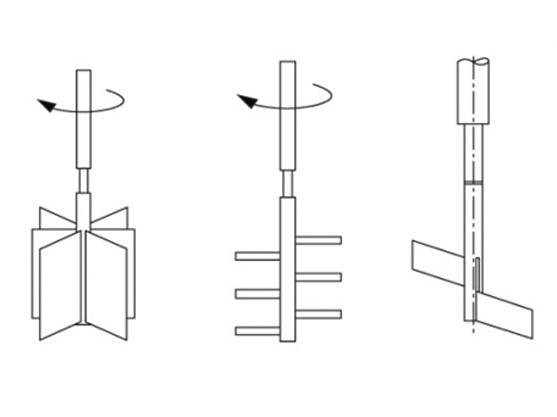
Figure 3: Krebs spindle (“paddle measuring geometry”; right), pin rotor (center), and vane rotor (left) [3]
The measurement is carried out after the “paddle” is immersed into, for example, a can containing the liquid sample. Typical can sizes which are commonly used in the paint industry are e.g. 1/2 liter (or 1 pint), 1/4 liter (or 1/2 pint), and 1 liter (or 1 quart). The measured torque values are displayed in Krebs units, abbreviated as KU.
Viscosity values cannot be determined in absolute units when using Krebs spindles since the rotating paddle, due to its geometrical shape, always performs a stirring process which generally generates turbulent flow with the formation of vortices. Since laminar flow conditions are not available, shear rate values cannot be calculated in principle. Therefore, all test results are to be considered relative values. Viscosity values specified in mPa.s or Pa.s by the manufacturer of these instruments are empirical determinations which are based on previously performed comparative tests. These relative viscosity values cannot be compared to absolute viscosity values which are measured when using absolute measuring geometries according to ISO 3219-2 or DIN 53019.
Paste spindles and rotors showing pins and vanes
Spindles and rotors in the form of pins and vanes are used when testing pasty materials which do not flow homogeneously, or with samples which contain large particles. Therefore, in principle, for these kinds of systems it holds that shear rate values cannot be calculated. Thus, the test results generally should be specified in terms of raw data, e.g. as rotational speed n in [min-1] and as relative torque Mrel in [%].
Pin rotors consist of several pins screwed at a right angle onto the rotational axis. Examples: spindles showing 6 pins, each one with length 20 mm or 50 mm and thickness 1 mm or 2 mm (see Figure 3, center) [3]. These kinds of rotors are also known under the name “paste spindles” (or RS).
For vane spindles, several rectangular vanes are attached radial to the shaft (see Figure 3, left), [3]. Examples are spindles showing 4 or 6 vanes with thickness 1.5 mm, the vane length L and the spindle diameter d (all in mm) showing L/d = 25/13, 43/22, 69/34, or 9/10, 16/22, 60/40. These kinds of spindles and similar ones are also known under the name “flag impeller” (or FL).
However, when using a vane rotor at high rotational speeds, there is the risk that the part of the sample in-between the vane areas might not be sheared at all, and that inhomogeneous, “plastic” deformation behavior might occur. In this case, the whole sample material enclosed between the vane areas might merely rotate in the form of an undeformed cylinder.
Vane rotors for testing gel-like samples
Foodstuffs like yogurt and other dairy products, desserts, and sauces often have an inflexible gel structure. This three-dimensional structure might already be destroyed when immersing a bob of a common standard cylinder measuring geometry into it or by the gap setting procedure when using a parallel-plate system. For these kinds of samples it is often preferable to select a vane system for the following reasons:
- Vane spindles can be immersed into shear-sensitive samples without changing their structural strength significantly. For example, a measurement might be performed directly in a glass container or in a can (“in situ”), immediately after the production of the sample and the filling process into containers.
- Since vane rotors do not have smooth cylindrical walls like standard measuring bobs, wall slip might be prevented, for example, when determining the yield point and the flow point. Usually here, the controlled torque method is selected. However, it should be taken into account that the measured values generally are relative values, and therefore should merely be presented in terms of raw data. This means: For rotational tests the following should be displayed in diagrams: the deflection angles φ [rad] or the rotational speeds n [min-1] versus the torque M [mNm] or the relative torque values Mrel in [%], respectively; and for oscillatory tests the following should be shown: φ and the phase shift angles δ [°] versus M.
Ball measuring systems (motion along a circular path)
Ball measuring systems have been developed for tests on semi-solid dispersions containing particles up to 5 mm in diameter [7; 1]. Typical samples are:
- Pasta sauce containing meat or chunks of tomato
- Multi-phase materials containing large particles or fibers such as construction materials, mortars, plasters, ceramic tile adhesives
- Coarse-grained dispersions showing separation or wall slip effects when testing, e.g. to investigate creep and flow of sludges, muds, and soil, for geological investigations to simulate the behavior of landslides and avalanches or of solifluction
- Jam or marmalade containing chunks of fruit
- Melting cheese with e.g. starch granules
These kinds of “ball measuring systems” consist of specially designed rotors and a cup with an inner diameter of approximately 115 mm for a sample volume of approximately 500 mL (see Figure 4). The rotors are designed as follows:
- An arm with the length L1 is mounted radially to the rotor shaft, projecting at a right-angle.
- At the outer end of this arm a pin with the length L2 is mounted right-angled pointing downwards
- at the end of this pin there is a sphere with the diameter d (called ball).
Balls with the following diameters are usually in use (all dimensions in mm): d = 15/12/8; the arm length L1 is between 35 and 40, and the pin length L2 = 30 approximately.
With the rotor in motion, the ball is drawn through the sample on a circular path showing the radius L1. It is only during the first rotation that the ball penetrates unsheared material which is not yet cleared of particles. However, even when performing only a single complete rotation, it is possible to obtain a flow curve over several decades of the rotational speed if a rheometer is used which is able to control the speed very quickly at each individual measuring point , e.g. in the speed range of n = 0.001 to 10 min-1.
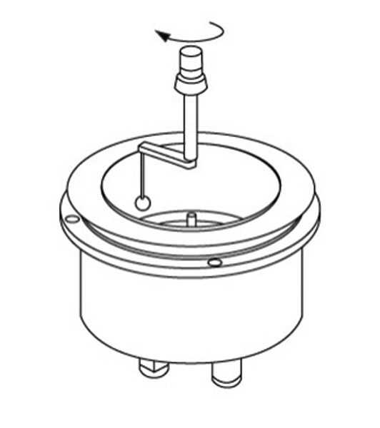
Figure 4: Ball measuring geometry: The ball moves along on a circular path.
The evaluation either uses raw data, i.e. rotational speed n and torque M, or is based on a so-called “dimensional analysis” and empirically obtained comparative values are taken by assuming conditions of a so-called displacement flow. Hence, analysis is not based on laminar flow conditions which are usually taken as a basis for the rheological analysis when measuring with absolute measuring geometries. This means the viscosity values which are obtained when testing with the “ball measuring system” are relative values which cannot be compared to the absolute viscosity values determined when using the standard measuring geometries according to ISO 3219-2 and DIN 53019.
Further relative measuring systems
Figure 5 shows some relative measuring systems which are used in industrial laboratories as stirrers for dispersions, for example, in the construction and food industry.

Figure 5: Relative measuring geometries as stirrers for dispersions; from left: (1) and (2) showing a helical shape, (3) for construction materials, (4) for starches, (5) a blade stirrer, and (6) with the shape of an anchor [3]
Conclusion
Relative geometries are in widespread use for diverse industrial applications. As relative measuring systems deliver relative values their comparability is limited; the values produced should therefore be compared only with other values determined with the same system or values produced by similar systems (same size, same geometry type). When these limitations are taken into consideration, relative measuring geometries provide useful results for simple quality control, also with difficult samples, including samples which cannot be measured properly with standardized geometries.
Read more about rheometry and rheological analysis in use
Take an in-depth look at rheological investigations on food
Order “Applied Rheology – With Joe Flow on Rheology Road” a book by rheology specialist Thomas Mezger for users of rotational and oscillatory rheometers
Browse the measuring systems provided by Anton Paar
References
[1] Mezger, T.G.: The Rheology Handbook, Vincentz, Hannover, 2020 (5th ed.)
[2] Mezger, T.G.: Applied Rheology – with Joe Flow on rheology road. Anton Paar, Graz, 2020 (7th ed.)
[3] ISO 3219-2: Rheology - part 2: General principles of rotational and oscillatory rheometry, 2020
[4] ISO 2555, Plastics — Resins in the liquid state or as emulsions or dispersions — Determination of apparent viscosity using a single cylinder type rotational viscometer method
[5] Barnes, H.A., Hutton, J.F., Walters, K.: An introduction to rheology. Elsevier, Amsterdam, 1989
[6] ASTM D562: Consistency of paints measuring Krebs unit (KU) viscosity using a Stormer-type viscometer. 2001 (2005)
[7] Müller, M., Tyrach, J., Brunn, P.O., Rheological characterization of machine-applied plasters, ZKG International, 1999